You are here
Cisco 思科交换机学习 有大用 有大大用
01) 01 NAT的优缺点
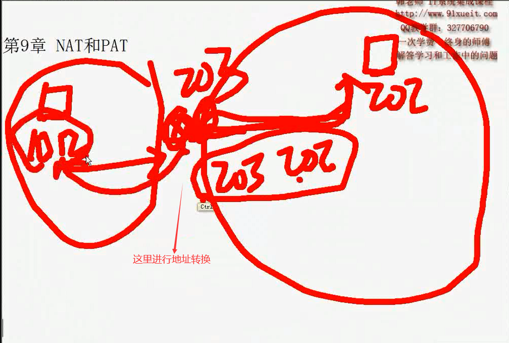
私网地址不能上网的,因为互联网上的路由器是不认识私网地址的(没有到私网上的路由表),所以互联网上的信息回不来
能上网是由于做了地址转换技术(NAT)

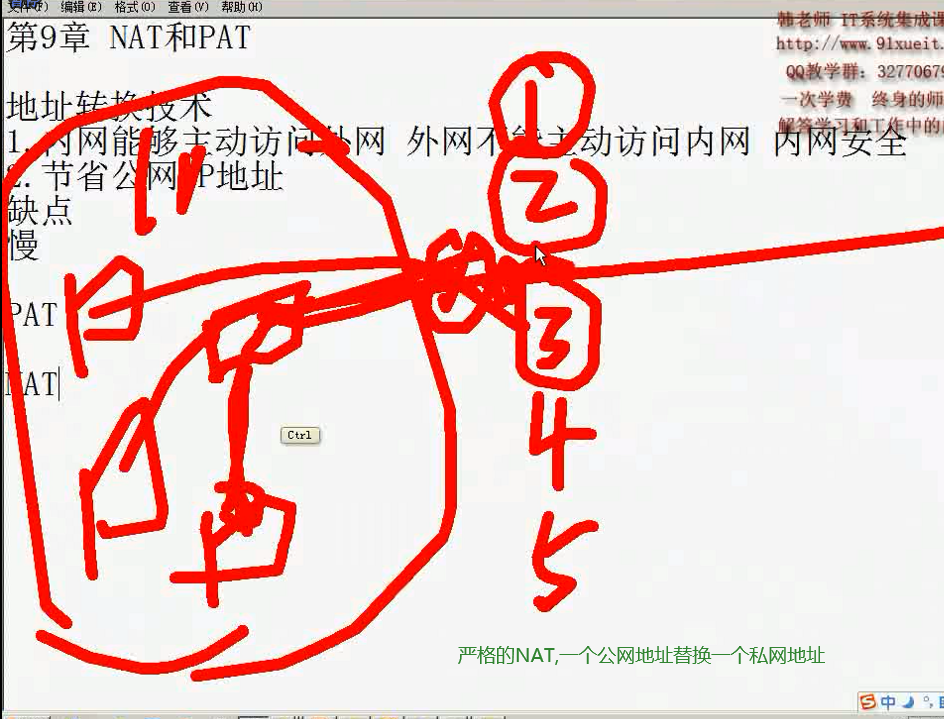
第9章NAT和PAT
地址转换技术
1.内网能够主动访问外网外网不能主动访问内网内网安全
2.节省公网IP地址
缺点
慢

02) 02 NAT的应用

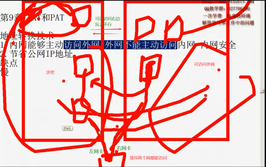
领导计算机插两个网卡,在领导计算机上配置一个路由(或连接共享)
把左边涉密当作内网,右边当作外网
当左边涉密访问右边时,用领导的右边的网卡地址替换
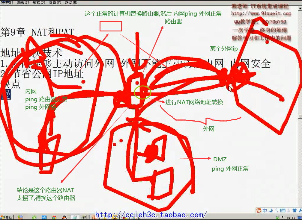
03) 03 NAT隐藏内网
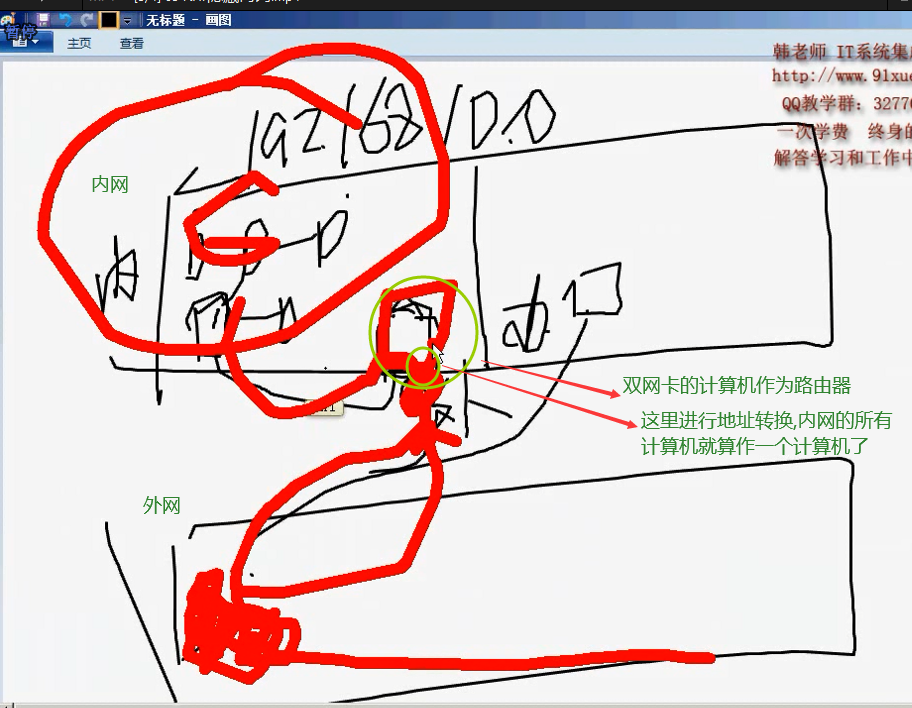
如上图,如果所有的计算机限速 网速为 100k/秒
那么内网中的所有的计算机的网速加起来就是 100k/秒,那太慢了,受不了
解决方法见下图
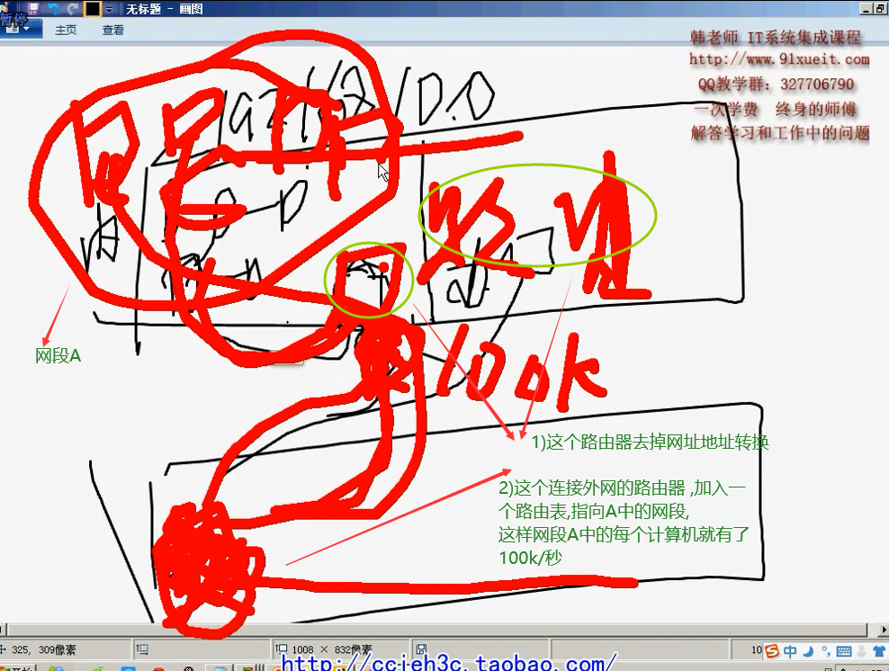
上图,网段A中的所有计算机上网的时候,就不采用NAT了,他们的源地址就是他们自己的 192.168开头的网址了
04) 04 NAT和PAT
NAT: network address translate,,严格的NAT,一个公网地址替换一 个私网地址(内网地址),,,,不节省公网地址,,,这种用得比较少
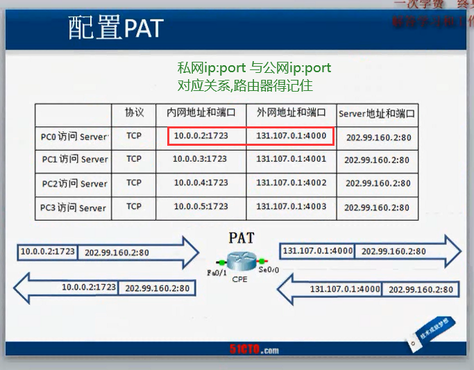
PAT: port address translate 节省公网IP替换源端口和源地址
一般情况下,我们的NAT,不严格的说法就是 PAT

05) 05 地址转换的类型
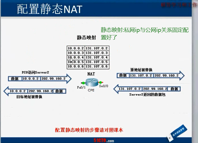
静态NAT:静态映射:私网ip-与公网ip关系固定配置好了,不常用
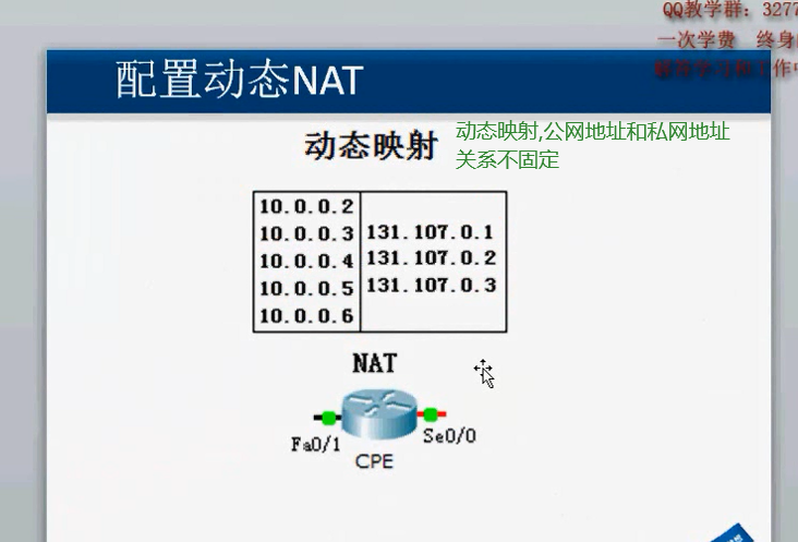
动态NAT:动态映射,公网地址和私网地址关系不固定
配置 PAT: 私网ip:port与公网ip:port 对应关系,路由器得记住
06) 06 在路由器上配置PAT
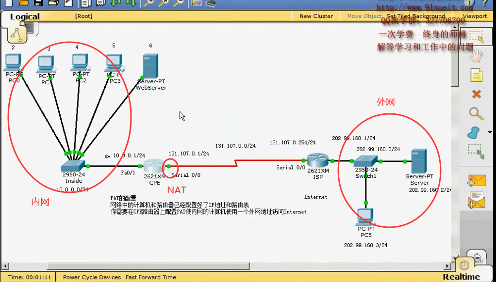
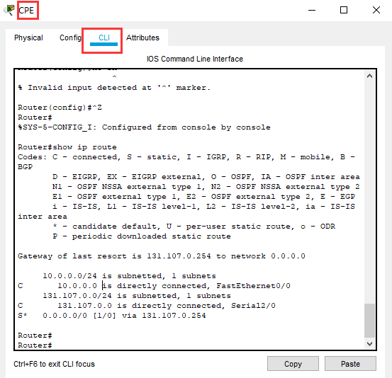
Router#show ip route #ECP 路由器有静态路由
Codes: C - connected, S - static, I - IGRP, R - RIP, M - mobile, B - BGP
D - EIGRP, EX - EIGRP external, O - OSPF, IA - OSPF inter area
N1 - OSPF NSSA external type 1, N2 - OSPF NSSA external type 2
E1 - OSPF external type 1, E2 - OSPF external type 2, E - EGP
i - IS-IS, L1 - IS-IS level-1, L2 - IS-IS level-2, ia - IS-IS inter area
* - candidate default, U - per-user static route, o - ODR
P - periodic downloaded static route
Gateway of last resort is 131.107.0.254 to network 0.0.0.0
10.0.0.0/24 is subnetted, 1 subnets
C 10.0.0.0 is directly connected, FastEthernet0/0
131.107.0.0/24 is subnetted, 1 subnets
C 131.107.0.0 is directly connected, Serial2/0
S* 0.0.0.0/0 [1/0] via 131.107.0.254
Router#
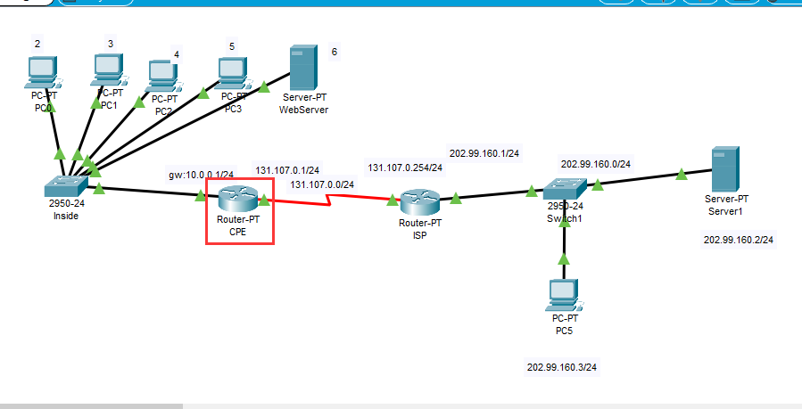
Router>en
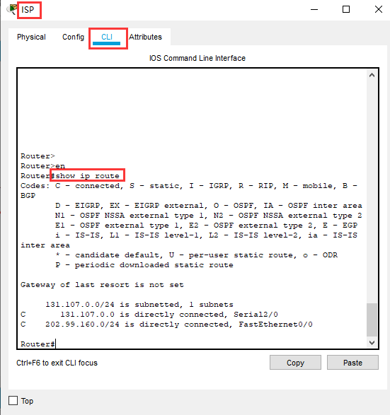
Router#show ip route #ISP 路由器没有静态路由
Codes: C - connected, S - static, I - IGRP, R - RIP, M - mobile, B - BGP
D - EIGRP, EX - EIGRP external, O - OSPF, IA - OSPF inter area
N1 - OSPF NSSA external type 1, N2 - OSPF NSSA external type 2
E1 - OSPF external type 1, E2 - OSPF external type 2, E - EGP
i - IS-IS, L1 - IS-IS level-1, L2 - IS-IS level-2, ia - IS-IS inter area
* - candidate default, U - per-user static route, o - ODR
P - periodic downloaded static route
Gateway of last resort is not set
131.107.0.0/24 is subnetted, 1 subnets
C 131.107.0.0 is directly connected, Serial2/0
C 202.99.160.0/24 is directly connected, FastEthernet0/0
Router#

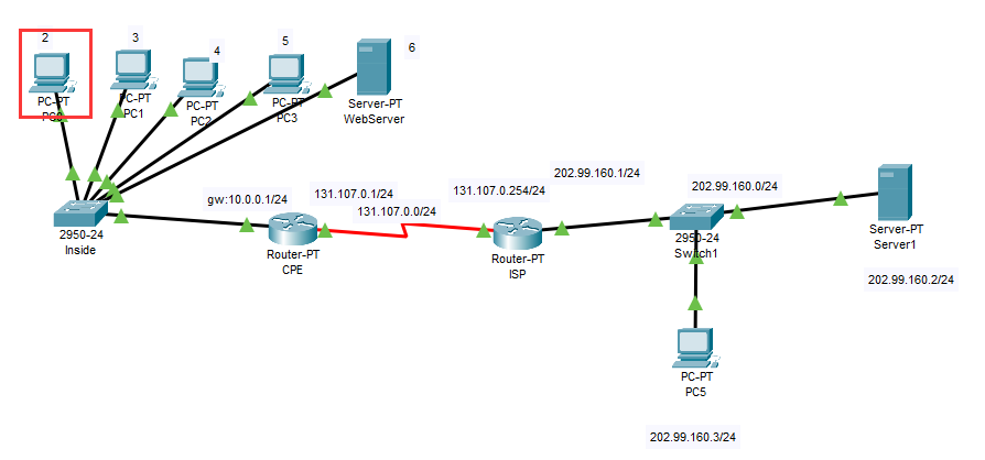
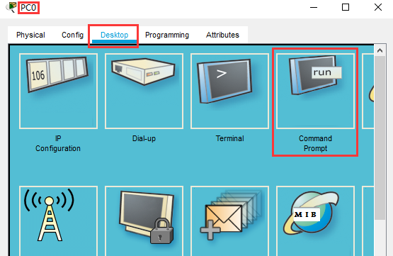
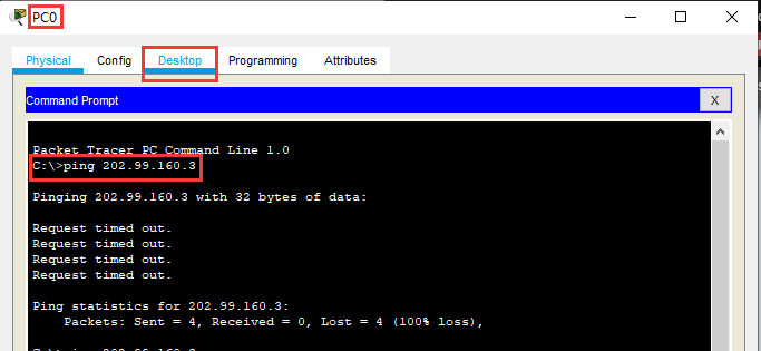
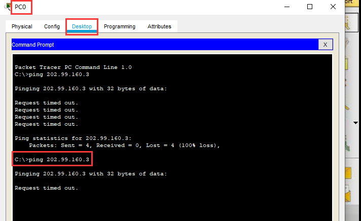
C:\>ping 202.99.160.3 # 不通
Pinging 202.99.160.3 with 32 bytes of data:
Request timed out.
Request timed out.
Request timed out.
Request timed out.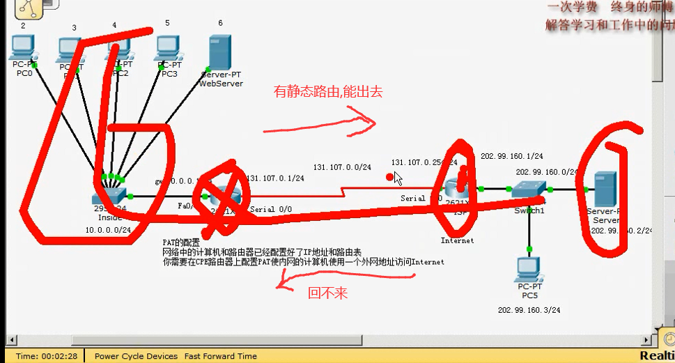
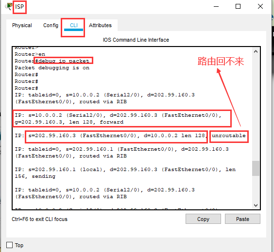
Router#debug ip packet #路由器上只要运行这个命令,过一任何一个数据包,它都会给你显示
Packet debugging is on
Router#
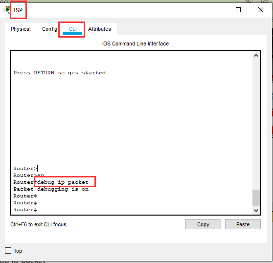
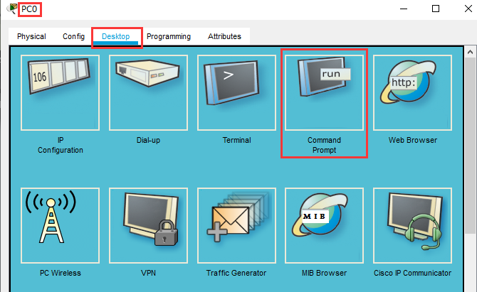
用左边局域网的一个电脑 ping 一下
由下图可见,路由回不来
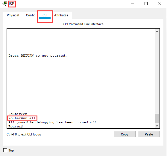
Router#un all #关掉所有调试模式
All possible debugging has been turned off
PAT
开启IP数据包转发显示,,真正的路由器上会发现一屏一屏的太多的数据
ISP#debug ip packet

下面进行 NAT 地址转换
在 CPE 路由器 只需要五步即可配置NAT
Router(config)#access-list 10 permit 10.0.0.0 0.0.0.255 #1) 在 CPE 路由器上定义 访问控制列表
Router(config)#ip nat pool todd 131.107.0.1 131.107.0.1 netmask 255.255.255.0 #2) 定义公网地址池 todd,,(todd是一个名称) ,,前面的 131.107.0.1 是第一个ip 地址,后面的 131.107.0.1 是最后一个ip 地址, 地址池里只有一个 131.107.0.1 ,,所以 前面的 ip 地址 和后面的 ip 地址相同
Router(config)#ip nat inside source list 10 pool todd overload #3) 把内网的访问控制列表和公网的ip地址池进行绑定
,,,,,inside source list 10 表示内网源的访问控制列表是 10 ,,,pool todd 表示外网的地址池是 todd ,,,,,overload(覆写) 表示 使用PAT ,如果没有overload 表示 使用 NAT
Router(config)#interface serial 2/0 #4) 指定外网
Router(config-if)#ip nat outside
Router(config)#interface FastEthernet 0/0 #5)指定内网
Router(config-if)#ip nat inside
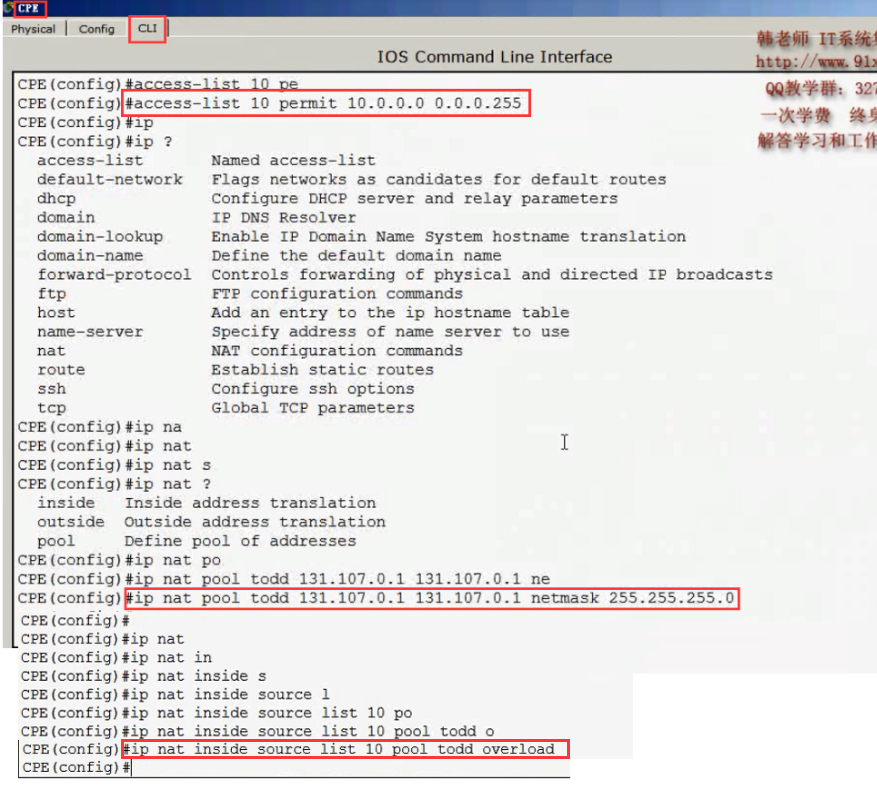
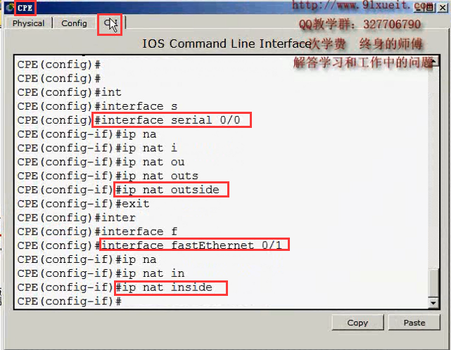
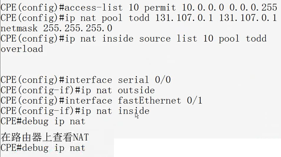
配置地址转换 就这三条命令,明白道理之后,很简单
CPE (config) #access-list 10 permit 10.0.0.0 0.0.0.255
CPE (config)#ip nat pool todd 131. 107.0. 1 131.107.0.1 netmask 255.255. 255.0
CPE (config)#ip nat inside source list 10 pool todd overload
Router(config)#interface serial 2/0 #指定外网
Router(config-if)#ip nat outside
Router(config)#interface FastEthernet 0/0 #指定内网
Router(config-if)#ip nat inside
在路由器_上查看NAT
CPE#debug ip nat
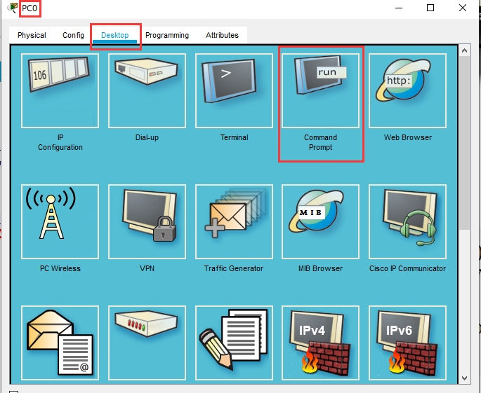
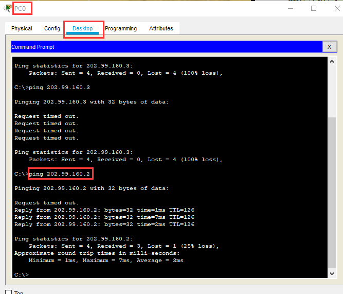
在内网的一个计算机上 ping 一下,,通了
C:\>ping 202.99.160.2
Pinging 202.99.160.2 with 32 bytes of data:
Request timed out.
Reply from 202.99.160.2: bytes=32 time=1ms TTL=126
Reply from 202.99.160.2: bytes=32 time=7ms TTL=126
Reply from 202.99.160.2: bytes=32 time=2ms TTL=126
Ping statistics for 202.99.160.2:
Packets: Sent = 4, Received = 3, Lost = 1 (25% loss),
Approximate round trip times in milli-seconds:
Minimum = 1ms, Maximum = 7ms, Average = 3ms
C:\>
在路由器上开启 debug 检查一下
Router#debug ip nat
IP NAT debugging is on
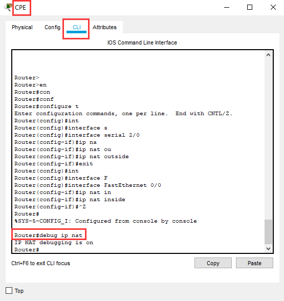
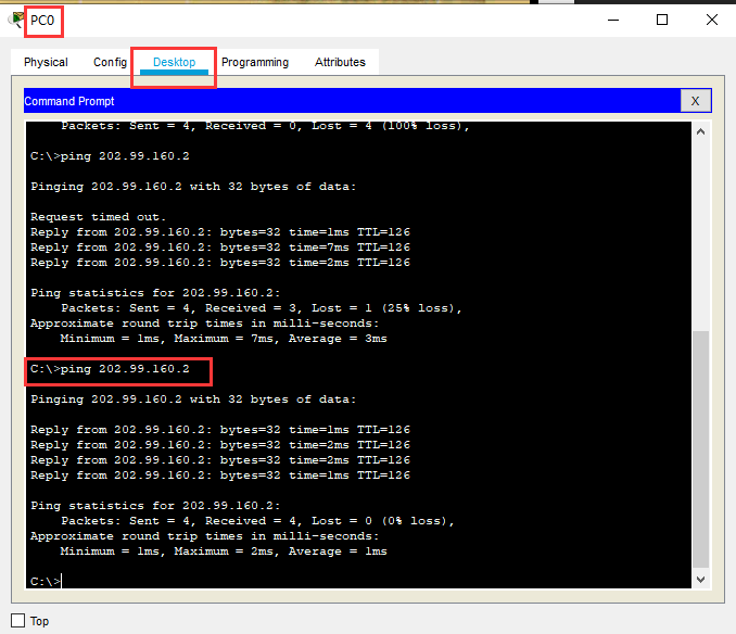
在一个内网的计算机上 ping 一下
C:\>ping 202.99.160.2
Pinging 202.99.160.2 with 32 bytes of data:
Reply from 202.99.160.2: bytes=32 time=1ms TTL=126
Reply from 202.99.160.2: bytes=32 time=2ms TTL=126
Reply from 202.99.160.2: bytes=32 time=2ms TTL=126
Reply from 202.99.160.2: bytes=32 time=1ms TTL=126
Ping statistics for 202.99.160.2:
Packets: Sent = 4, Received = 4, Lost = 0 (0% loss),
Approximate round trip times in milli-seconds:
Minimum = 1ms, Maximum = 2ms, Average = 1ms
C:\>
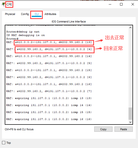
可以看到 出去正常 回来正常
07) 07 在Windows上配置NAT 准备环境
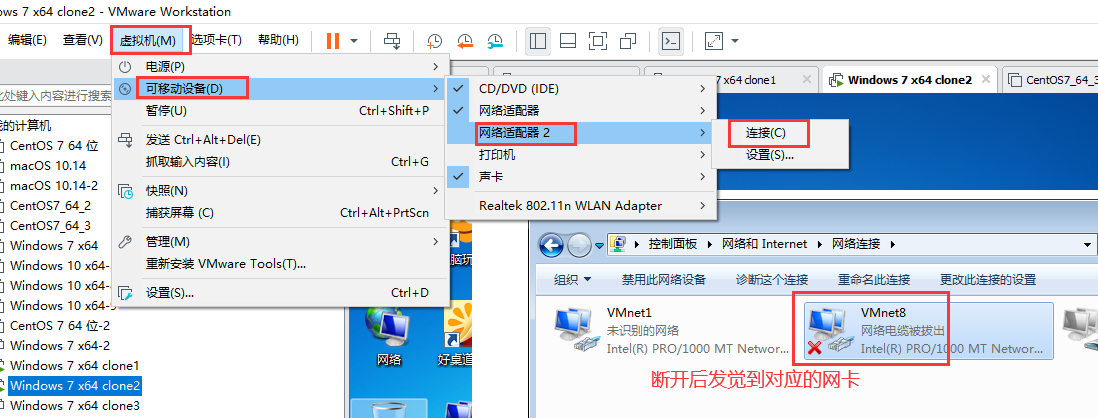
如下两图,断开后发觉到对应的网卡
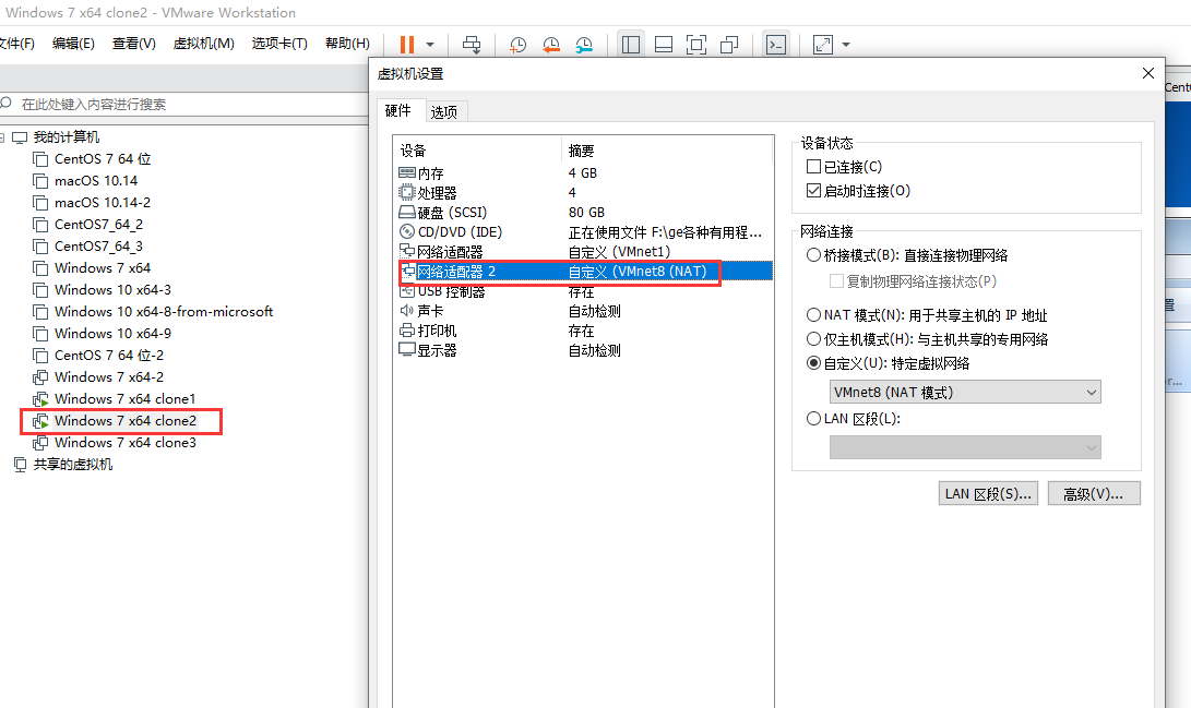
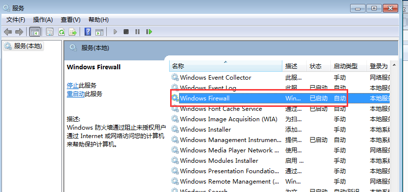
两个电脑 A 能ping 通B,B不能ping通A,那么检查不能被ping 通的电脑(这里就是A电脑) 的防火墙是否停止并禁用 和ipset和是否禁ping (如果是 windows 2012 的禁ping 见 /node-admin/19931 )
防火墙
ipset
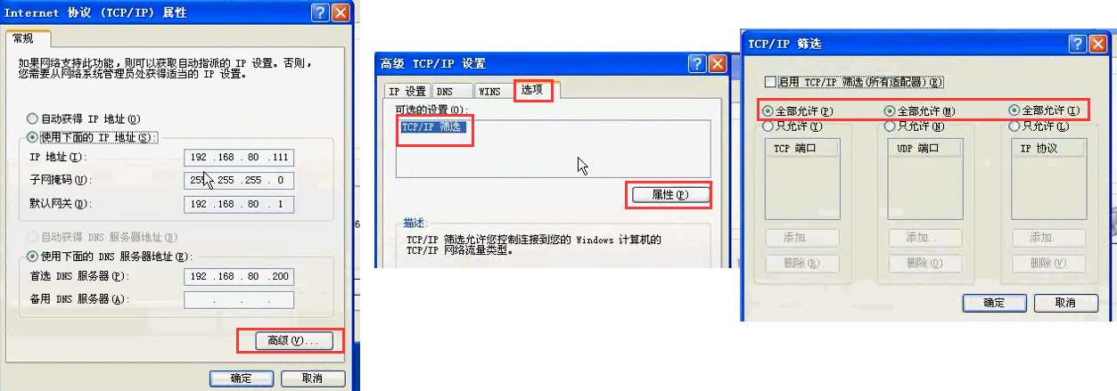
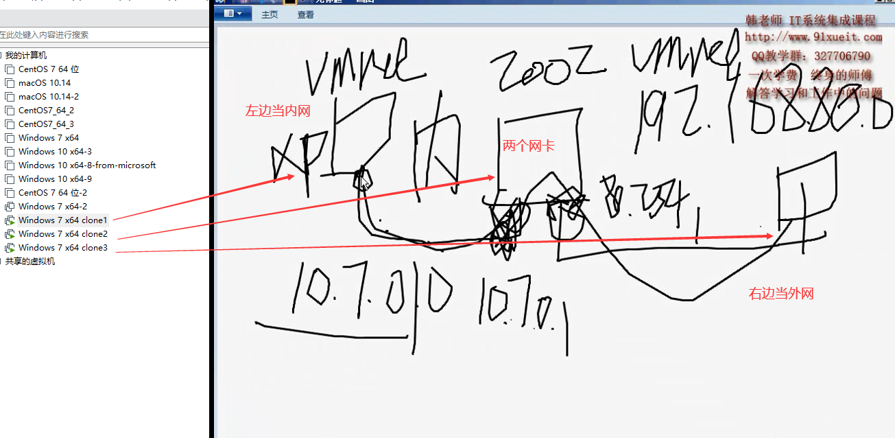
几个电脑配置后
内网电脑,关掉防火墙后 ,能ping 通中间两个网卡的电脑,不能 ping 通 右边外网的电脑
这里内网电脑是不需要设网关的 (我感觉需要设置网关,让默认的ip怎么走)
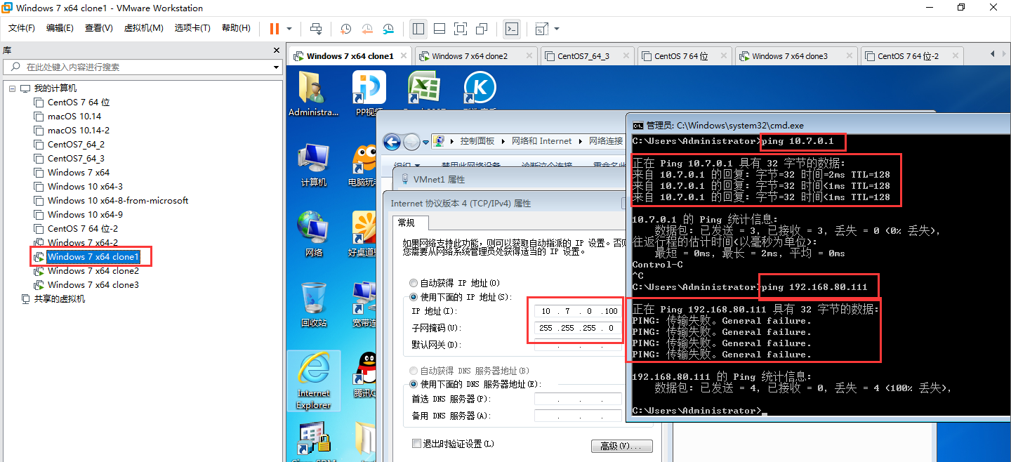
中间两个网卡的电脑,关掉防火墙后 , 能ping 通左右两个电脑
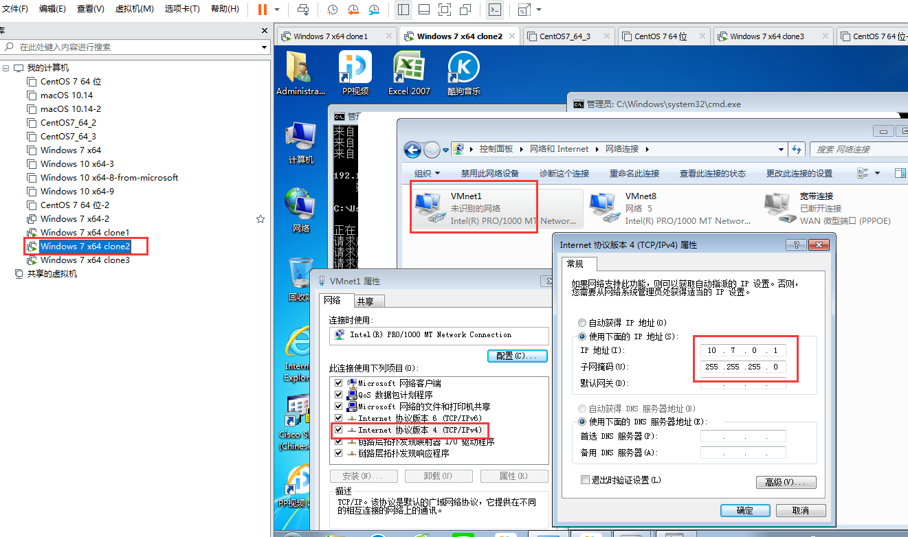
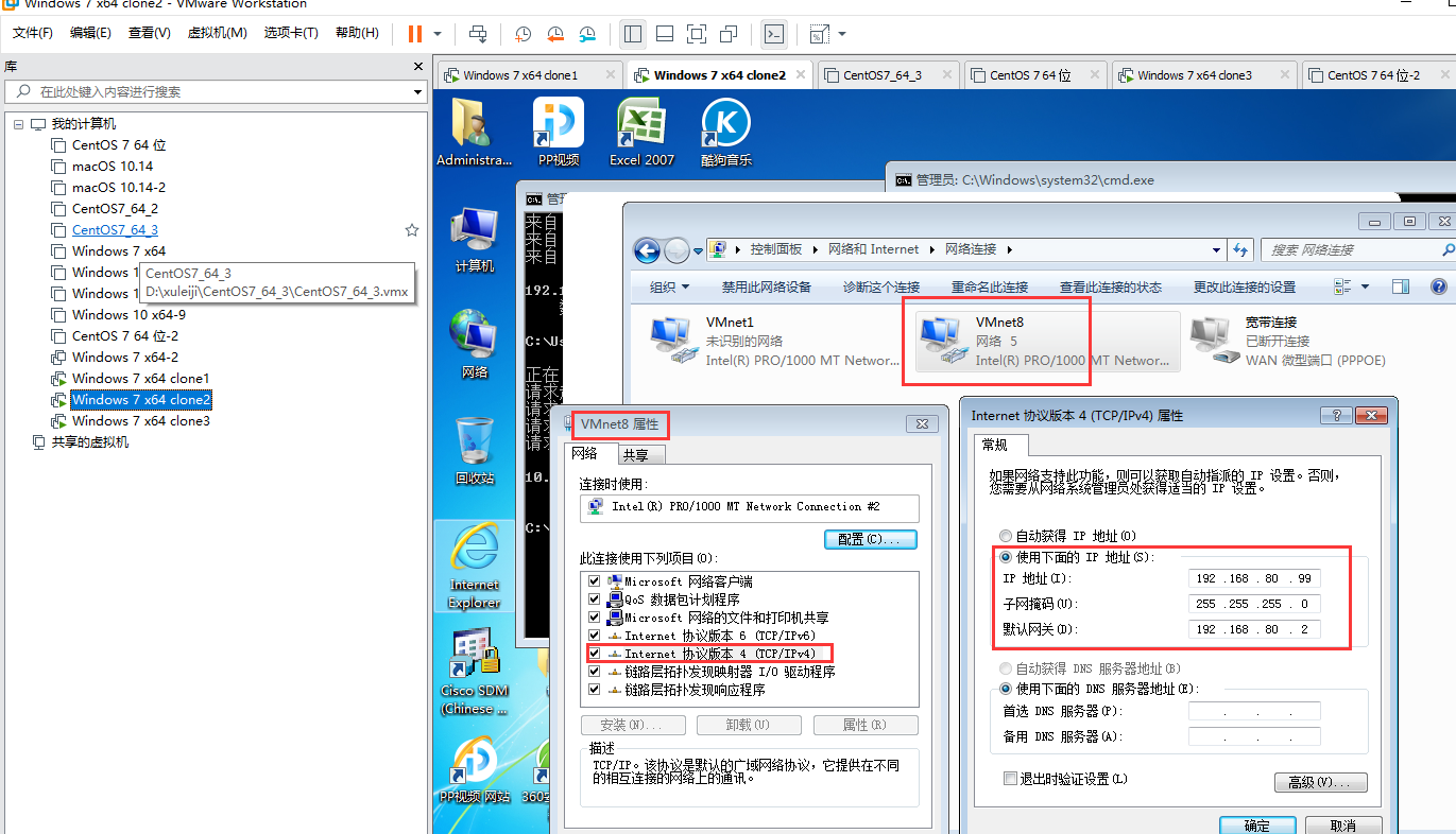

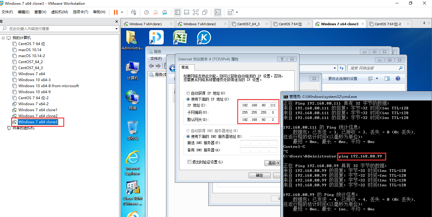
右边外网的电脑,能 ping 通中间网卡的电脑
08)08 在Windows上配NAT
我们把 上面的 windows 7 x64 clone2 替换为 windows server 2012
windows server 2012 上面 要安装 "路由和远程访问" 才能在管理工具中看到它
安装方法 见 /node-admin/19920
配置 windows server 2012 的网卡 与 ip 地址 与 windows 7 x64 clone2 一样
中间两个网卡的电脑(windows server 2012),关掉防火墙后 , 能ping 通左右两个电脑
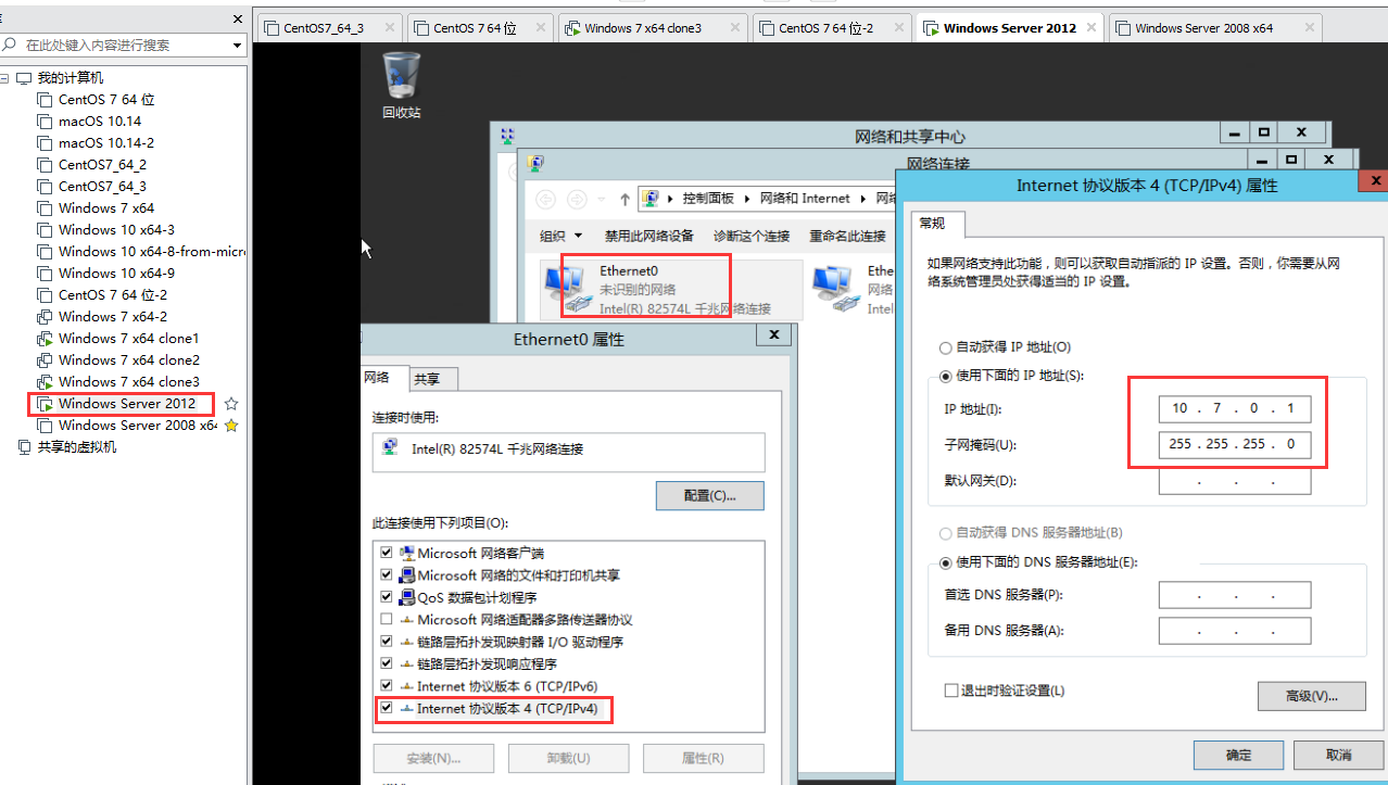
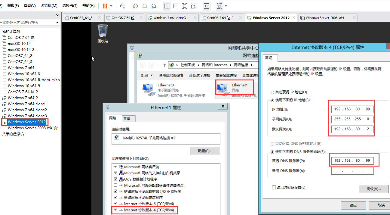
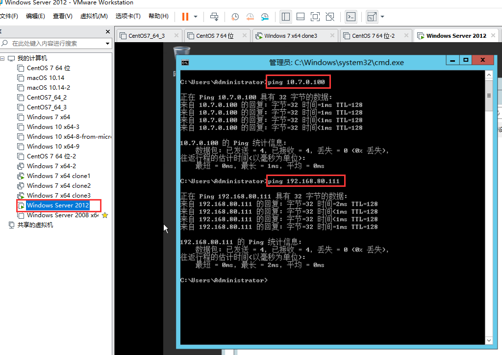
windows 2012 默认是禁 ping 的(别人 ping 不通 windows 2012 ),启用ping的处理方法见 /node-admin/19931
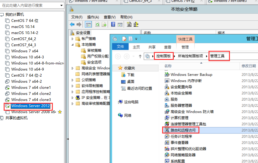
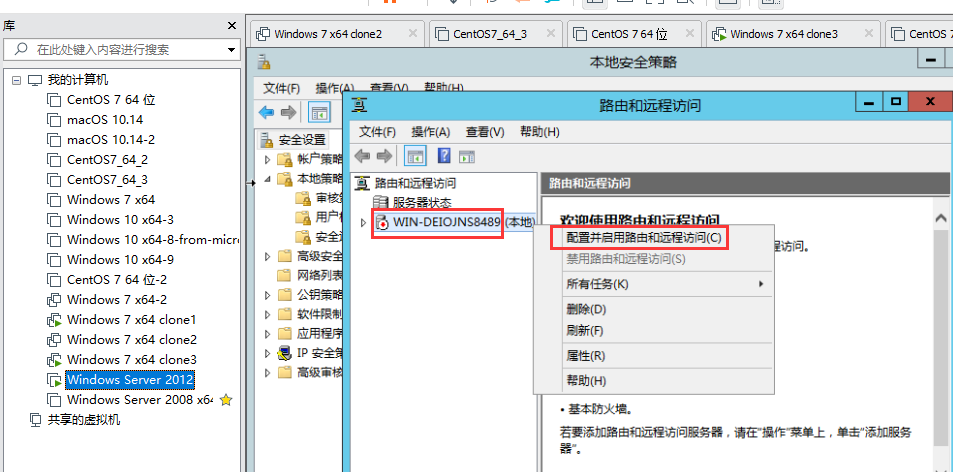
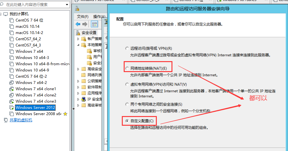
下图是 NAT 的配置
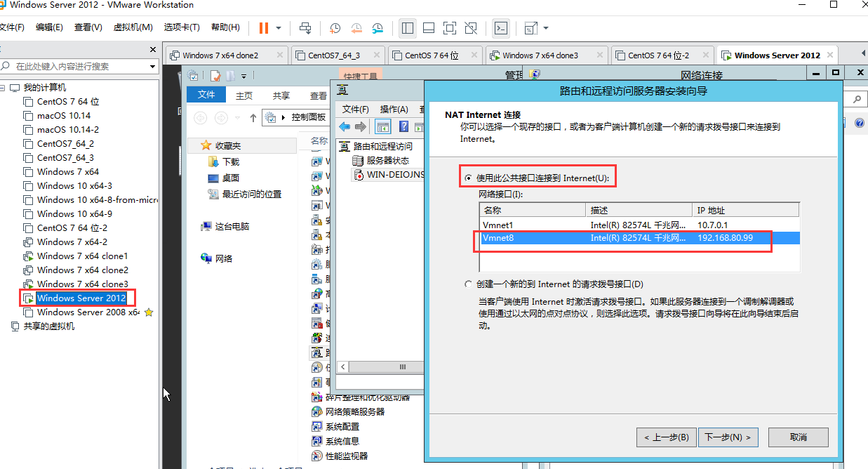
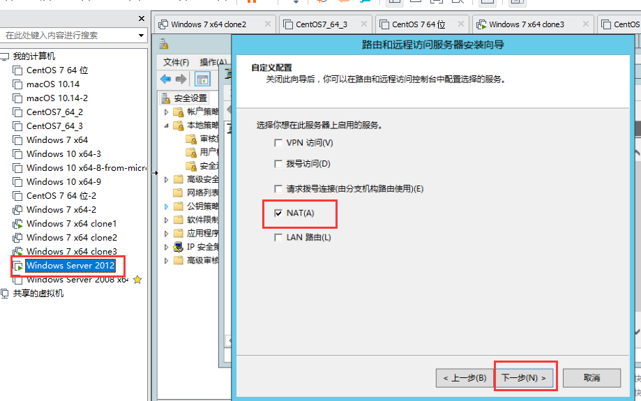
下图是自定义配置
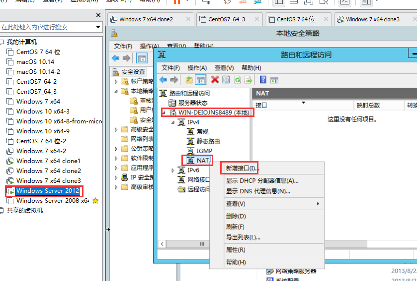
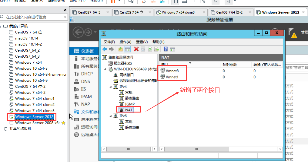
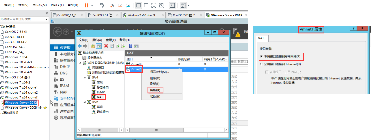
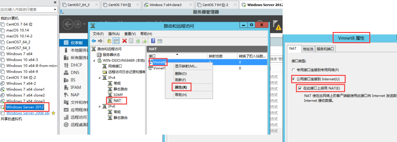
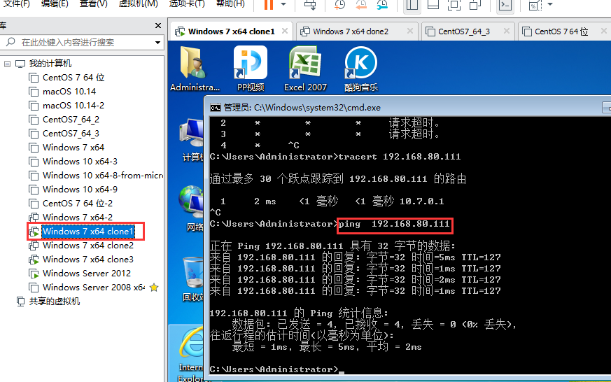
内网计算机 windows 7 x64 clone1 是可以 ping 通 外网计算机 windows 7 x64 clone3
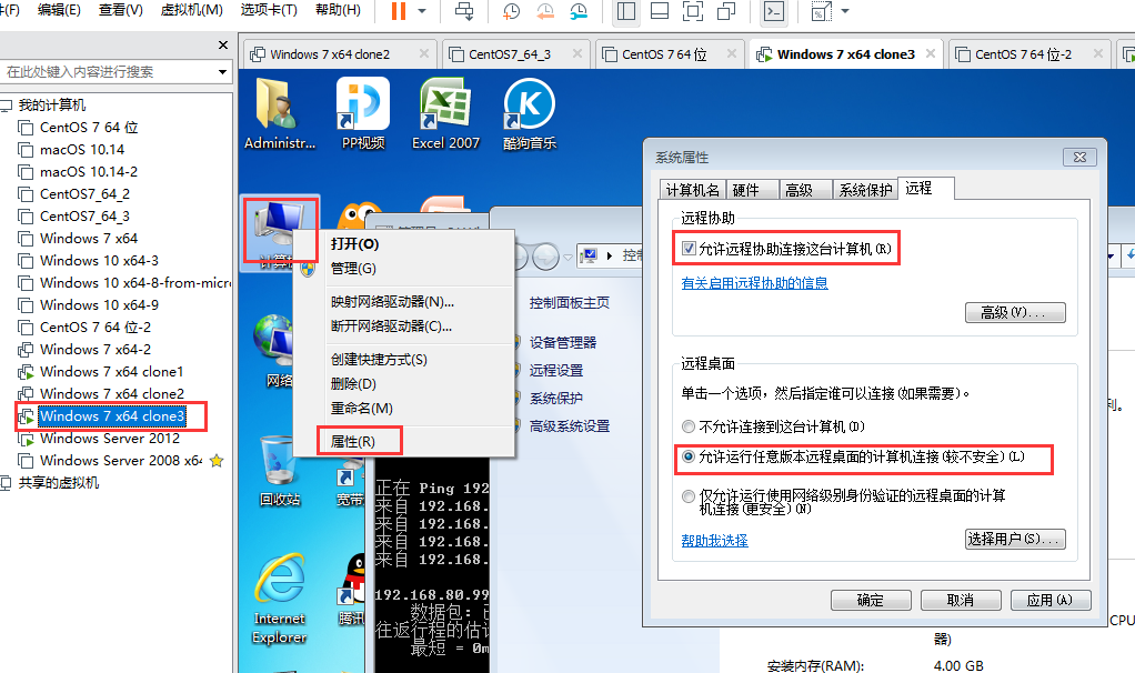
外网计算机 windows 7 x64 clone3 启用远程桌面
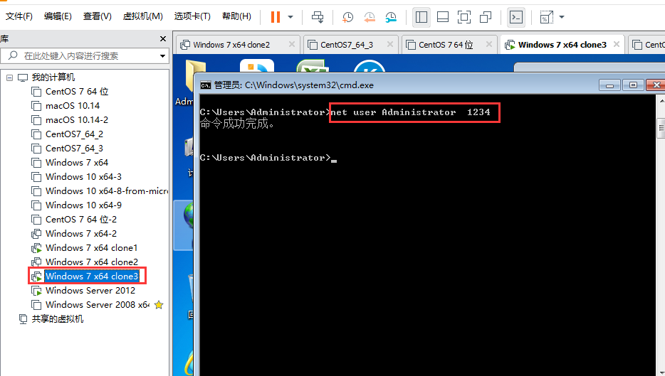
外网计算机 windows 7 x64 clone3 启用远程桌面 的连接密码 为 1234
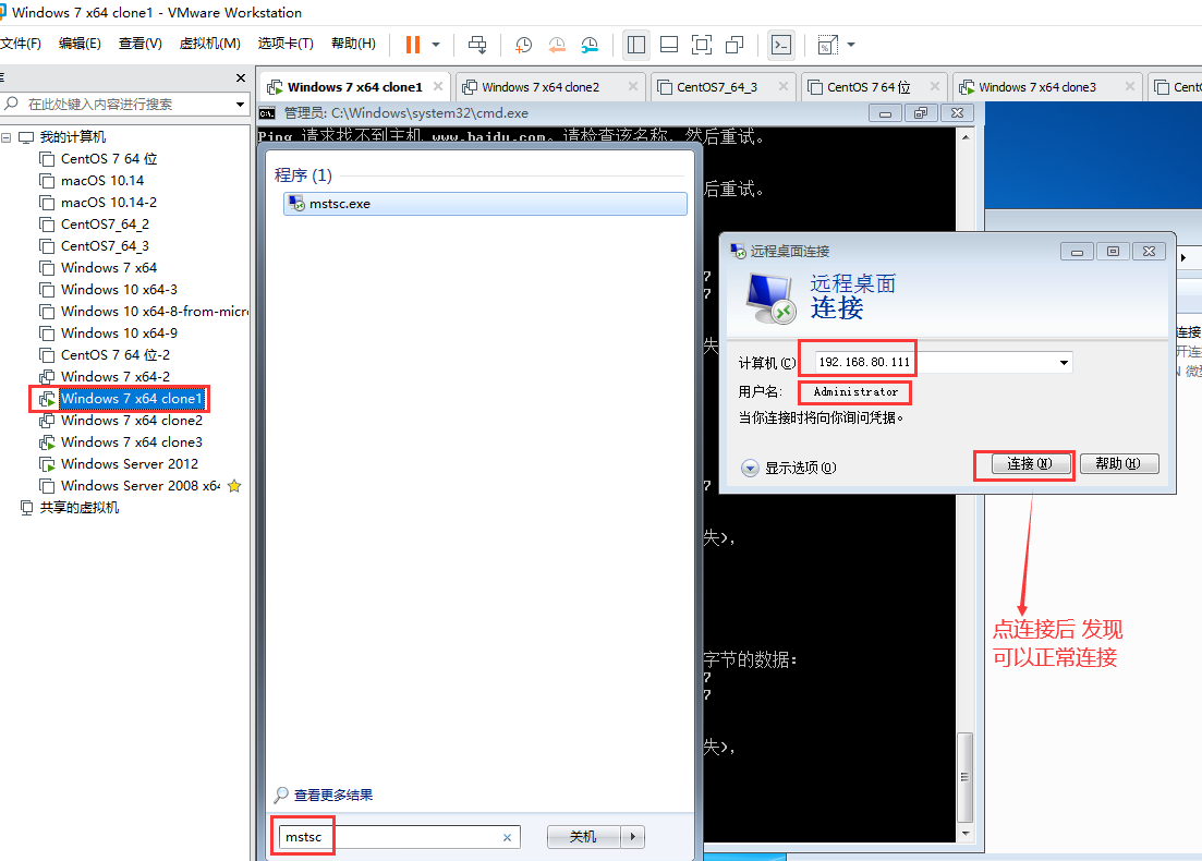
内网计算机 windows 7 x64 clone1 可以远程连接 外网计算机 windows 7 x64 clone3
09) 09 在Windows上配置连接共享
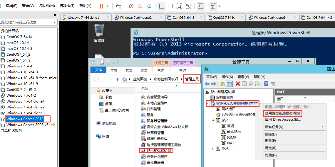
中间两个网卡的电脑(windows server 2012) 关掉 "路由和远程访问" 如何关掉 见 /node-admin/19938
所有的 windows 上都有网络连接共享的功能
有两块网卡时 才有连接共享的功能
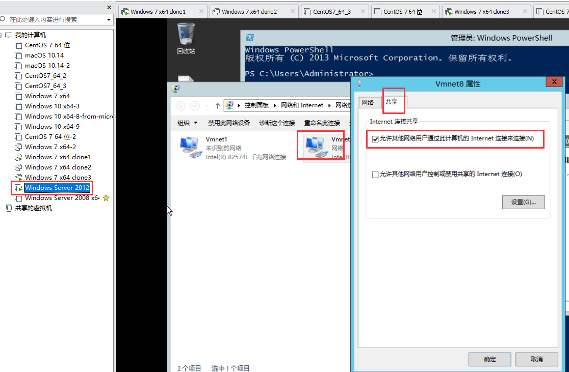
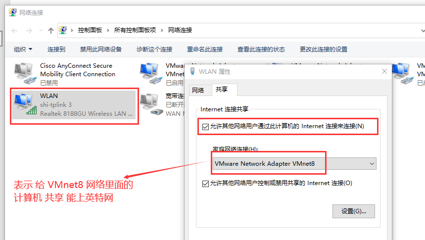
中间两个网卡的电脑(windows server 2012)
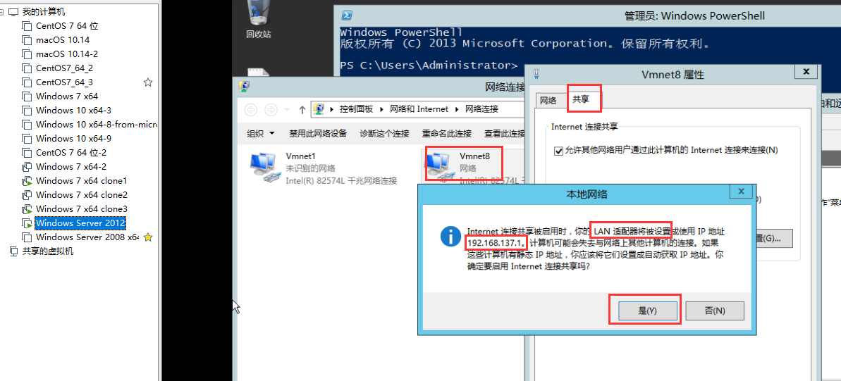
Internet连接共享被启用时.你的LAN适配器将被设置成使用IP地址
192.168.137.1 (192.168.0.1) 计算机可能会失去与网络上其他计算机的连接。如果
这些计算机有静态IP地址,你应该将它们设置成自动获取IP地址。你
确定要启用Internet连接共享吗?
让内网网卡 设置192.168.137.1,,这是 windows 的一个bug,,我们再到 内网网卡重新设置一下 ip 地址为 10.7.0.1
中间两个网卡的电脑(windows server 2012) ,,内网网卡,把 ip 地址 由 192.168.137.1 改回 10.7.0.1
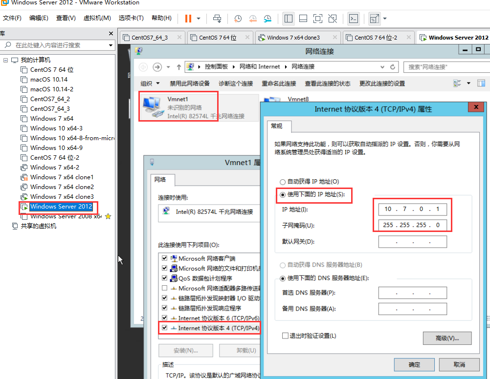
内网计算机 windows 7 x64 clone1 是可以 ping 通 中间两个网卡的电脑(windows server 2012) 和 外网计算机 windows 7 x64 clone3
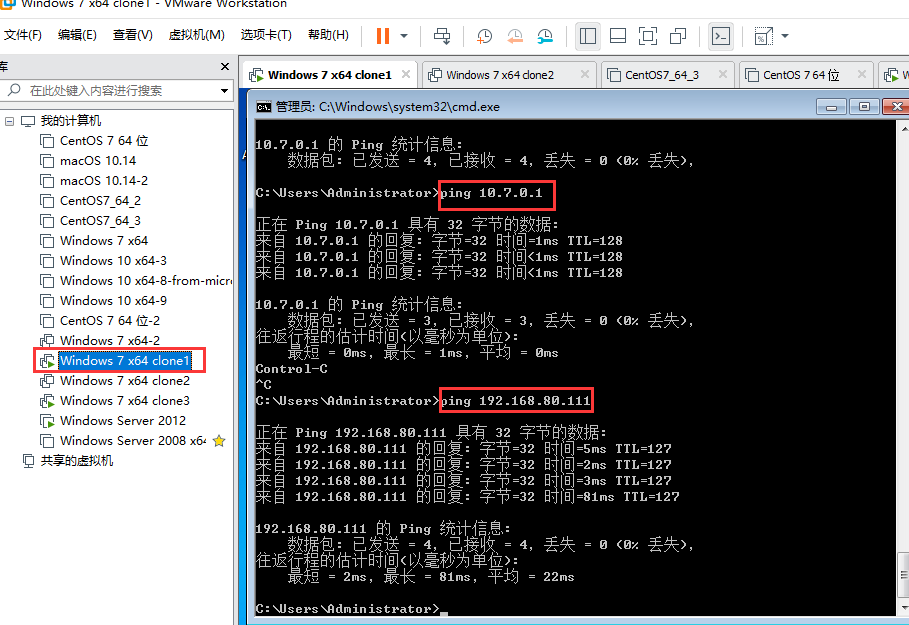
配置网络连接共享其实就是内网的一个NAT
10) 10 端口映射的作用
外网访问内网的web服务器,要配置端口映射
内网的一个计算机A 可以作为跳板机,来访问其它的内网,,,外网的计算机只要能够访问这个内网的计算机A就可以了

端口映射允许你使用公网地址访问内网服务器
11) 11 在路由器上配置端口映射
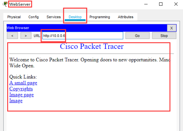
WebServer
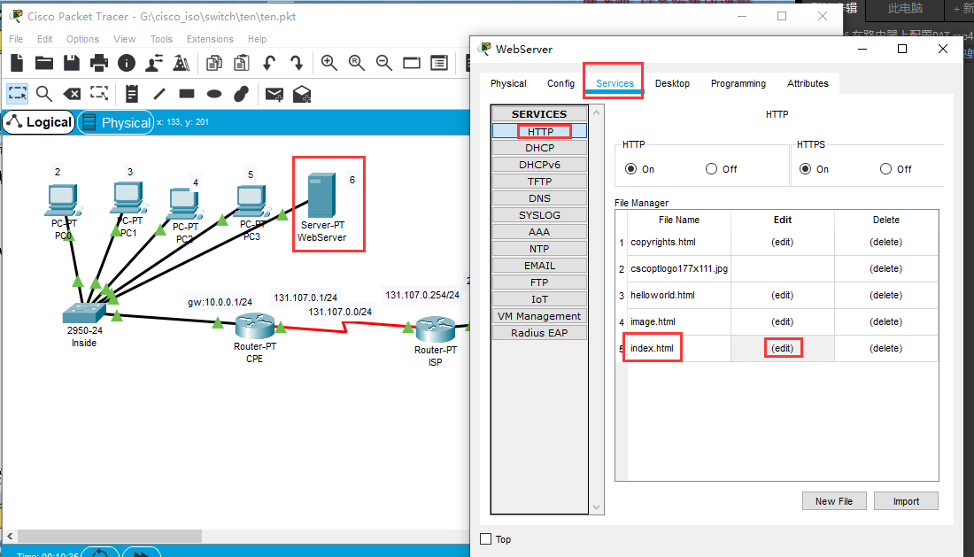
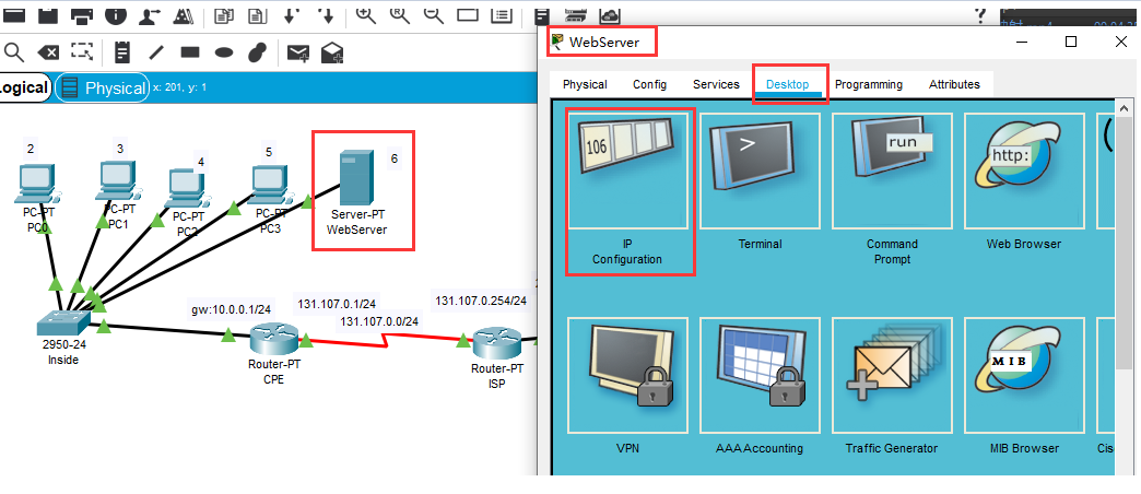
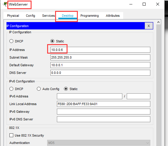
在内网可以访问 (这里是自己访问自己)
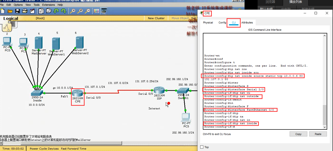
配置静态的端口映射 在 CPE 路由器上 只需要三步即可
Router>en
Router#conf
Router#configure t
Enter configuration commands, one per line. End with CNTL/Z.
Router(config)#ip nat inside source static tcp 10.0.0.6 80 131.107.0.1 80 #1) 配置静态端口映射 指定内网和外网 ,,使用tcp协议 10.0.0.6 80是内网ip和端口,,, 131.107.0.1 80 是外网ip和端口
Router(config)#interface Serial 2/0
Router(config-if)#ip nat outside #2) 指定这个网卡接口为外网
Router(config-if)#exit
Router(config)#interface FastEthernet 0/0
Router(config-if)#ip nat inside #3) 指定这个网卡接口为内网
Router(config-if)#
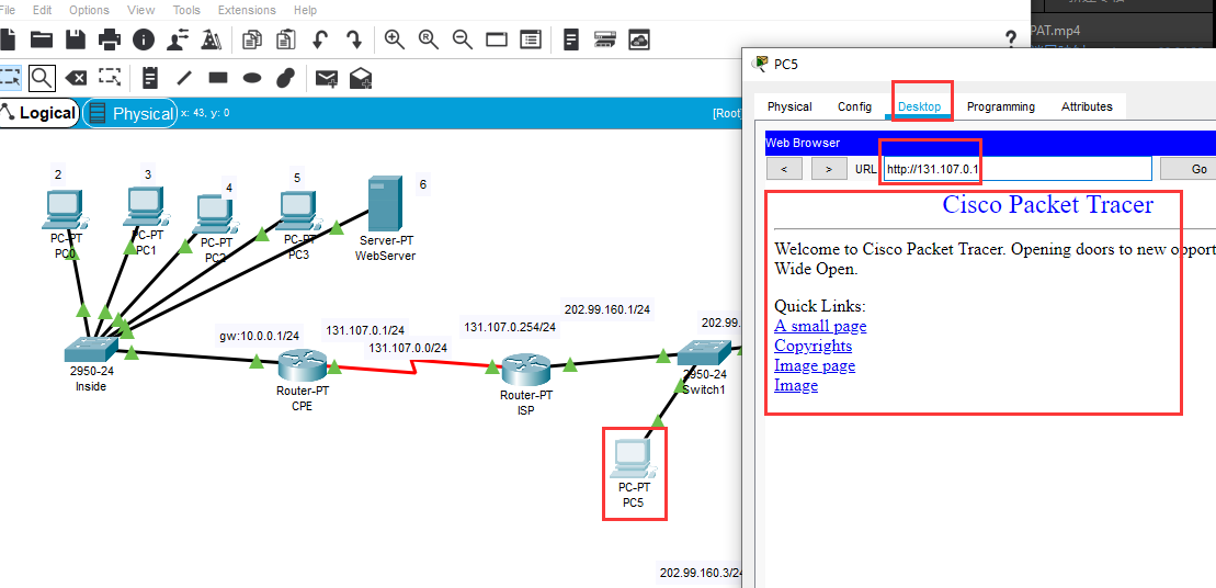
在外网的计算机上 可以打开这个内网的计算机的 web 网站了
12)12 在Windows连接共享和NAT上配置端口映射
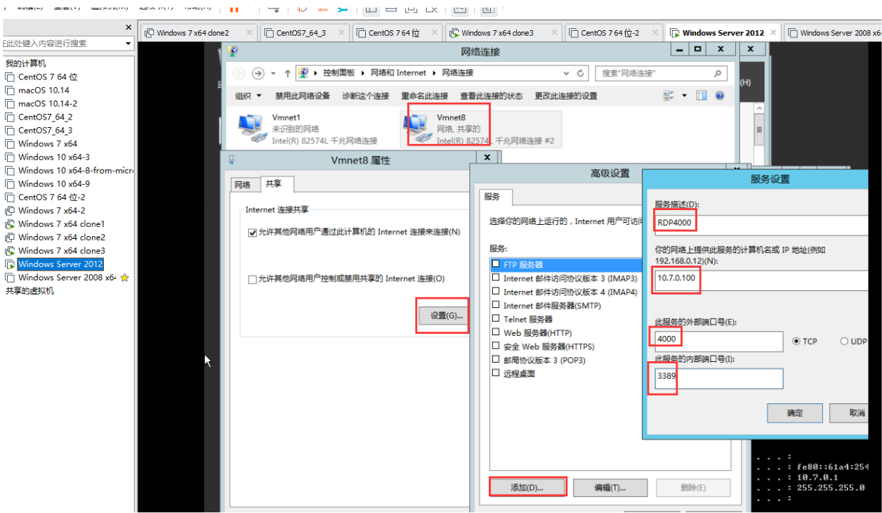
中间两个网卡的电脑(windows server 2012) VMnet8(外网网卡)配置一下静态的端口映射
表示 外网的计算机,访问 中间两个网卡的电脑 的 4000 端口时,映射到 内网 (计算机 windows 7 x64 clone1) 10.7.0.100 的 3389 的端口
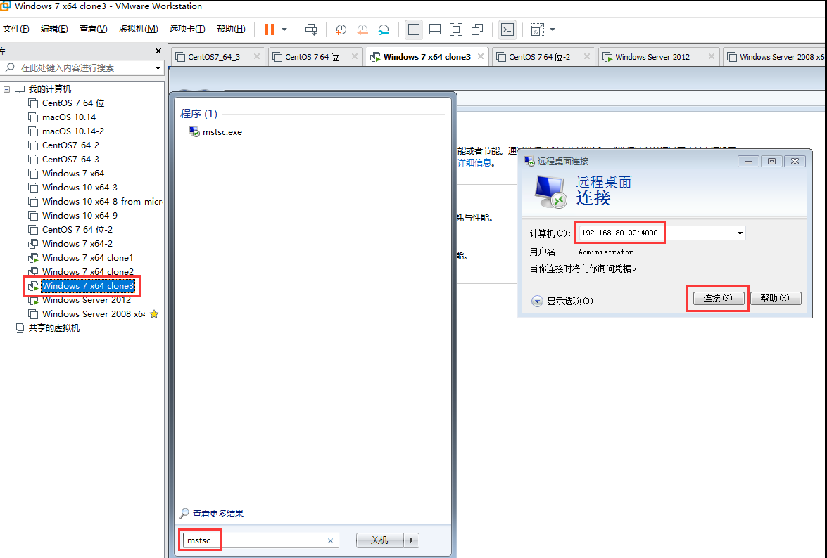
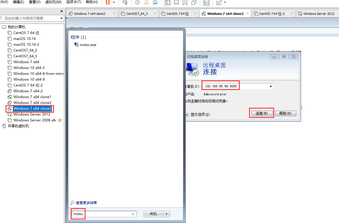
此时 外网计算机 windows 7 x64 clone3 是能够连接内网计算机 windows 7 x64 clone1 的 ,,使用的是外网地址和端口 192.168.80.99 4000
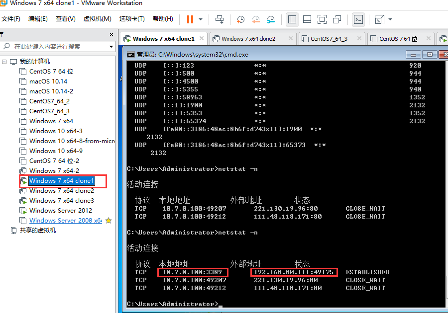
内网计算机 windows 7 x64 clone1 通过 netstat -n 可以看到 有人连接到 本机的 3389 端口了
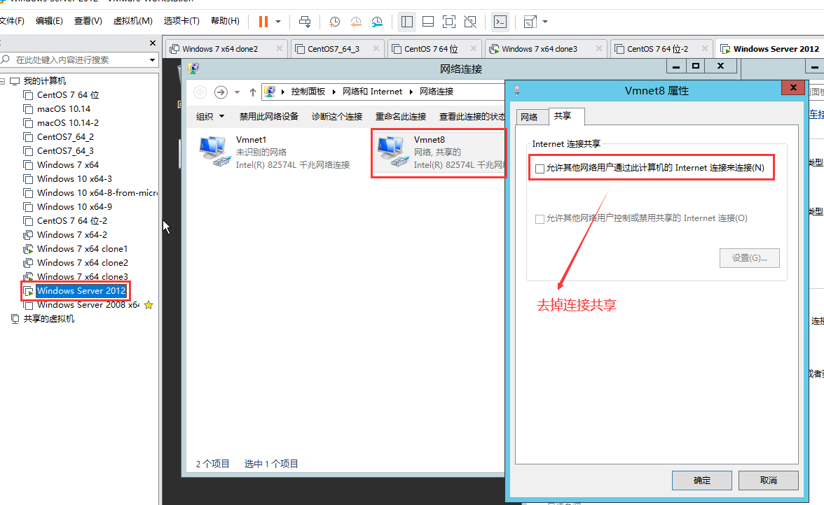
中间两个网卡的电脑(windows server 2012) VMnet8(外网网卡) 去掉连接共享
照着 08) 配置一下 路由和远程访问 (要禁用并且停止防火墙 (本页面 搜索 “防火墙" 可以看到如何禁用)和 网络连接共享服务)
然后 如下图 配置静态端口映射
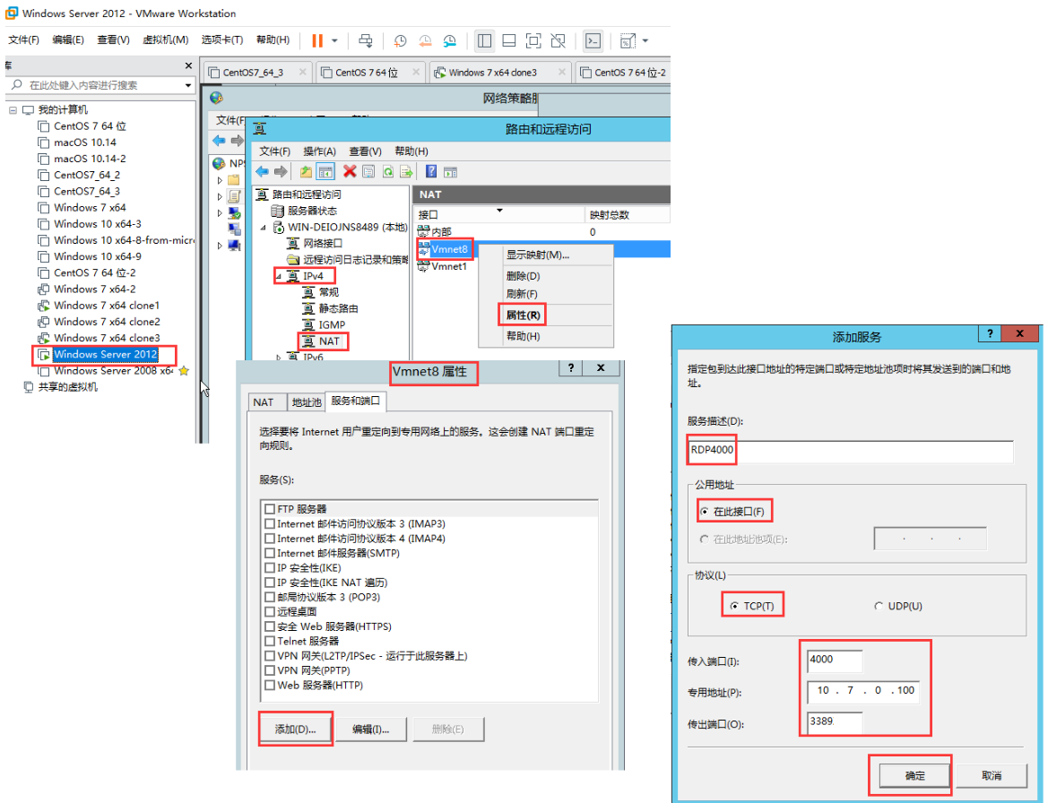
同样,,,此时 外网计算机 windows 7 x64 clone3 是能够连接内网计算机 windows 7 x64 clone1 的 ,,使用的是外网地址和端口 192.168.80.99 4000
